How can we help?
Scytec Status Relay Controller
Overview
The Status Relay Controller (SRC) is a mini PLC programmed to work with DataXchange. The SRC comes pre-programmed and ready to work with DataXchange out of the box. Every SRC is programmed identically and the configuration is done with the expressions. DataXchange will poll the SRC and retrieve the status of each of the inputs and assign the status values to the SRC variables so they can be used in expressions.
The Standard SRC has 8 inputs. By default all 8 Inputs can be used for Equipment Status and each of these inputs are mapped to a variable allowing standard DataXchange expressions to be used to evaluate the status of the attached equipment. The SRC can be configured to have the an input used for a part counter and have that input associated with the SRC part count variable.
The Extended SRC has 8 additional discrete inputs as well as 4, 4-20 milliamp input connections. The additional discrete inputs can be used to track additional points on the machine such returning a High or Low value to the SRC. Another feature is allowing any of the extended 8 digital inputs to return data as an integer within DataXchange. There is more detail on the integer conversion here.
Both versions of the SRC have 6 outputs and each output is mapped to a continuous and pulsed variable allowing standard DataXchange expression to be used to control devices connected to the SRC outputs.
SRC Standard Configuration
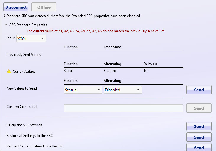
The SRC has options that can be set by sending data to the SRC. Using the built in interface, DataXchange can easily send the needed data to adjust the SRC configuration. The user interface can be found under the Communication tab under SRC Properties. From there you will have access to the additional SRC configuration options.
When the Connect button is pressed the SRC will attempt to connect and detect the SRC. Once a connection is made the configuration changes can be sent to the SRC. When an actual connection is made the Connect button will change to Disconnect. When disconnected all of the Send buttons will be disabled, and when connected they will all be enabled. While connected any data received as a response will be displayed in the large text box on the bottom of the screen.
Settings can also be set for the SRC in Offline mode. This will allow the settings to be restored to the SRC at a later time.
Once connected to the SRC it is possible to able to modify the following settings.
- X Input Functions: You are able to select and modify settings for inputs X1-X8.
- X Previously Sent Values: These are the settings that are saved in the database for the selected input.
- Current Values: This is the current value for the selected input.
- New Values to send: This setting can be adjusted to have 4 different options: Status (the default), Latching Low, Latching High and Counter.
- Input Delay: When Off is selected the Delay(s) text box will be hidden. If On is selected then the Delay(s) text box will be shown. The text box will accept positive integers less than 1000. More on this topic can be found here.
- Custom Command: Used to send a custom command. Custom Commands are only used by Scytec support personnel.
- Query the SRC Setup: This will return the current setup of the SRC. Details such as firmware version, sending input state, sending input states on change, automatic sending of the input states and any delays that are set.
- Restore all settings to the SRC: This function can be used when replacing an SRC, or when SRC settings were configured offline. All of the previously saved settings will be sent to the SRC.
- Request Current Values: This will return the current values for each of the SRC inputs.
- Offline: SRC properties can be accessed in an offline mode. Standard and extended properties can be saved but not sent to the SRC.
SRC Extended Configuration
The SRC has an extended option that will allow the user to take advantage of 8 additional discrete inputs as well as 4, 4-20 milliamp input connections. The additional discrete inputs can be used to track additional points on the machine such returning a High or Low value to the SRC. Another feature is allowing any of the extended 8 digital inputs to return data as an integer within DataXchange. There is more detail on the integer conversion below.
When the Connect button has been pushed it will interface with the SRC using the associated communication parameters (TCP or serial). When the connection is made the Connect button will change to Disconnect. When disconnected all of the Send buttons will be disabled, and when connected they will all be enabled. While connected any data received will be displayed in the large text box on the bottom of the screen. Once connected to the SRC it will automatically detect that an extended SRC is being used and additional option will become available.
Once connected to the SRC, it is possible to modify the Scaled range and the Digital conversion of an integer. The allowed input range for all 4 analog inputs is 4 – 20 mA. Within DataXchange the input can be scaled to the appropriate range. Using the image below, and having the max value set at 100 and the min value set at 0, if the analog input receiving had a value of 12 mA the value returned to the [SRC.AI01] variable would be 50.
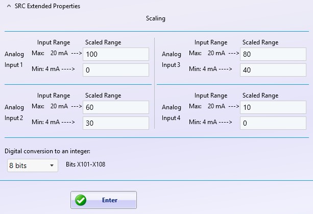
In addition to being able to return values of High and Low, the SRC X101 – X108 inputs can be used to calculate an integer value depending on which inputs are being energized. The integer value is returned to the [SRC.integer] variable. It is possible to choose whether the conversion is calculated using 2 – 8 bits. The default setting is 8 bits. If multiple inputs are energized, the values are added together. For example using the chart below if X101 and X103 energized, the total value being returned to the [SRC.integer] variable would be 5.
| SRC Value when energized | Bit | |
|---|---|---|
| [SRC.X101] | 1 | On by Default |
| [SRC.X102] | 2 | 2 |
| [SRC.X103] | 4 | 3 |
| [SRC.X104] | 8 | 4 |
| [SRC.X105] | 16 | 5 |
| [SRC.X106] | 32 | 6 |
| [SRC.X107] | 64 | 7 |
| [SRC.X108] | 128 | 8 |
One of the best example cases to use for the [SRC.integer] variable would be to track overrides on a legacy machine. Connect each wire on the override knob to the X inputs on the extended SRC. As the override knob is turned up or down the integer value in the [SRC.integer] variable with change, allowing expressions to be used to work with the override levels within DataXchange.
SRC Delay Timer
The Input Sending Delay functionality on the SRC is used in the scenario where an input must be in a certain state for a period of time before the state should be considered to have changed. An example is a stack light that can be continuously on or in a blinking state. If the stack light is capable of blinking and the blink rate is every 3 seconds then the input sending delay can be set to 5 seconds. Only after the input has been in the same state for more than 5 seconds will the SRC change the state of the input.
In addition, if the state of the input alternates more than twice then that status of the input will be reported as an A for alternating, instead of the standard H or L indicating High or Low.
The input delay can be enabled or disabled by sending a string using the following syntax:
inputDelay:[port]:[state]:[duration]|
[duration] is only needed if the [state] is ON
To enable the input delay on port 1 with a delay of 10 seconds the following string would be sent:
inputDelay:X1:ON:010|
To enable the input delay on port 3 with a delay of 5 seconds the following string would be sent:
inputDelay:X3:ON:005|
To disable the input delay on port 2 the following string would be sent:
inputDelay:X2:OFF|