How can we help?
Create a Shop Floor Layout
Overview
This will guide will demonstrate the steps required to create a customized shop floor layout screen within the Real Time Viewer. The Shop Floor Layout view can be customized to display many different types of data such as machine status colors, part counts and status times. Detailed information about available data items can be found here.
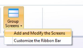
- Go to RTV → Group Screens or My Screens → Add or modify the screens.
- Add a new screen and enter a name. Click Next.
- Assign the view called shop floor layout.
- Configure the view.
- To start, use the Browse button to load in the image from a source file. The most commonly used image is a wire framed top down view of the shop floor but anything can be used even a blank image or solid color.
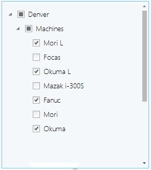
- Once an image is chosen, select the machines that will be displayed on the Shop Floor Layout view. There is not a limit to how many machines you can select for the view.
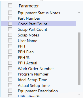
- Now select the parameters needed to display on the canvas that is being created.
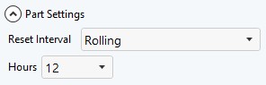
- Below select how part counts will be displayed.
- The font size will reflect in any of the parameters selected.
- The Status Symbol can be used for may different things, such as outlining a machine or creating a custom view from a blank canvas. For this demonstration we will show how to create a custom shape. Do this by selecting Polygon from the drop down, then click and drag the slider to select the desired transparency value. For most applications half transparency will still keep the images below visible.
- Once everything selected is ready to go click the Add button located at the bottom of the screen.
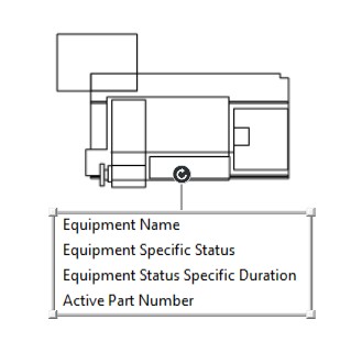
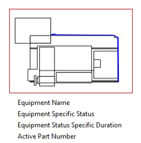
- An image of all of the selections should now show up on the canvas and look something like this.
- Click and drag the items to the corresponding location on the canvas. If an item is added accidentally or misconfigured, it can be deleted by right clicking on the items and selecting delete.
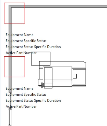
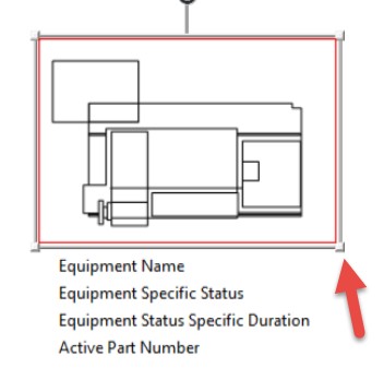
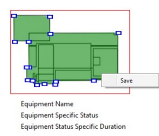
- Click and drag the polygon over the item that will be using a custom shape ensuring that the red square covers the entire thing. Grab and modify the shape of the square by clicking on any corner and dragging it. Something to note, the red square is the boundary for drawing. Double clicking within the red square will allow drawing to occur, right click to select to save the changes.
- Once properly positioned double click at the starting location then start outlining the desired shape. Use the mouse to outline and click on each corner as it gets built out.
- Once the image has been completely traced, right click the mouse. Then adjust the image by using the blue squares. When finished, right click the mouse and save.
- Now repeat steps 13 through 16 for each individual machine. Once finished, click Enter and Save the RTV Screen.